Introduction
In our last blog, we described our history with markerless motion tracking dating back to 2009 with early shape fitting methods. We discussed the benefits we saw with AI based tracking methods and, our view of the future of markerless tracking as described in this short video. In this blog we will share our early experience with three of the AI based markerless systems that have powered acceptance of this technology (SwRI, KinaTrax, and Theia 3D). We will place special emphasis on the data generated from each system together with that of a marker-based system. I think you will be just as surprised by what we experienced as we were.
Objectives
But first, it must be said, this is not an attempt to validate any of these systems nor to compare or evaluate one as better than another. The work we did in our early assessment does not have the necessary rigor to arrive at those conclusions. Rather our basic question was simply how accurate is this new technology? What can we do with it? We found there is more to that question than one would think!
There are few validation studies, none that cover multiple systems, and no real way to compare different systems. We’ve all seen the skeletal overlays in the troves of marketing data. How do you measure the accuracy of data derived from these videos? Guidance is often expressed as the subject should cover at least 500 pixels. So, working through the math, a 1-pixel feature extracted from a 6 foot subject would have an accuracy of 2.7 centimeters? Ok, that is resolution. But overlays which are valuable for throwing out the obvious misalignments offer little in terms of data quality.

Our questions were pretty basic. How do data compare among systems? Are the data reasonable in terms of the movement? Do the data show repeatable and predictable patterns? Are the data useable in higher order computations such as joint forces, moments and power? Do systems do better in one type of activity than another?
Methods
To answer these questions, we used The MotionMonitor’s hybrid capabilities to synchronously collect data from an optical based marker tracking system and 8 digital video cameras, and then created 4 standard biomechanical models using the data generated by each of the 4 technologies. The optical system was a Vicon 8 camera Vero (2.2 MP) collected at 100hz. The digital video system was an 8 camera Basler Ace2Pro (set to 1.2 MP) also collected at 100hz. The system was calibrated to a common global reference frame. The video cameras were calibrated as proscribed by each of the markerless technologies using extrinsic readings common to all. Four, standard 18 segment models with 21 joints were created using data generated by each of the four technologies. The marker-based subject used rigid body clusters to track each segment with joints located using a digitizer and appropriate offsets from digitized points to joint centers.
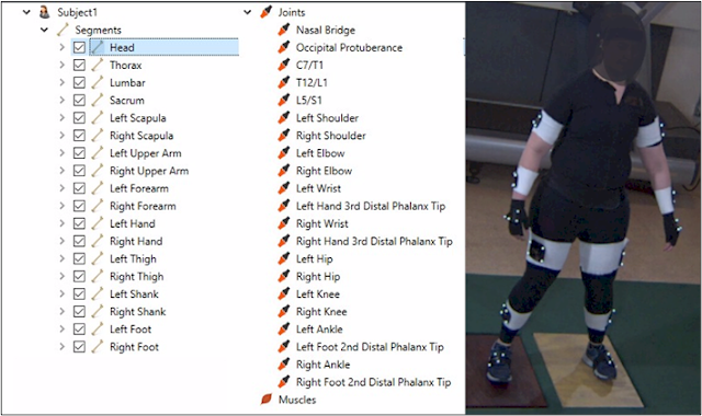
In most cases, the markerless technologies generated joint data directly. When it did not, joint data was inferred from other reported features. For example, the knee joint center might be located as the centroid of condyles or the toe as offsets from other foot features. Each markerless technology generated 4×4 transformation matrices to locate segments in the global reference frame. Data was collected for an over ground gait walk, treadmill running, a counter movement jump, and a throwing activity. All data was smoothed using a Butterworth 4th order 12hz digital filter. The output screens identify the subjects as Marker, MLess1, MLess2 and MLess3 which is not the same order as listed in the first paragraph😊
Results
To address our questions, we first looked at the joint separations of each markerless subject relative to the markered subject. In addition, we looked at the absolute reporting of position data, joint angles, acceleration data, joint forces and moment data for each subject. We’ll discuss each in turn.
Joint Separations
In the screen shot from The MotionMonitor below (Figure 1), we have displayed the subjects generated by each of technology. The subject generated by Marker data is in blue, MLess1 is in white, MLess2 is in yellow and MLess3 is in pink. They are remarkable for the degree of overlap.
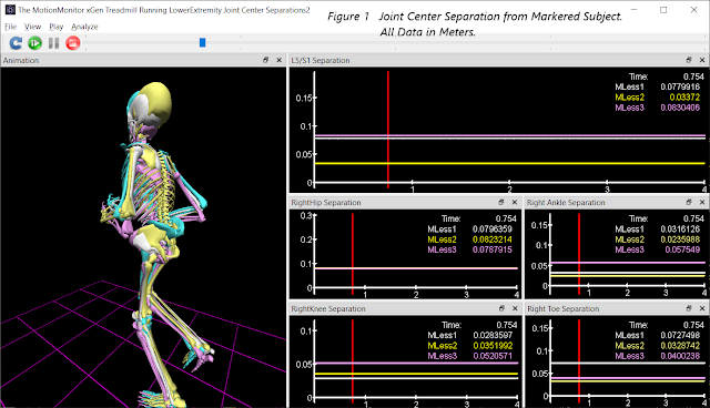
To determine how closely the markerless data tracked with the markered data, we computed the average separation between the markered subject’s joint centers and each of the markerless subjects. These were averaged over a 1 second interval in the treadmill running trial. We were surprised at how tightly they align. You may need to zoom in on the image to read the graphical data (all data are in meters) but are summarized below in centimeters.
MLess1 MLess2 MLess3 MLess1 MLess2 MLess3
L5/S1 7.8 2.7 8.3
Right Hip 8.0 8.2 7.9 Left Hip 9.0 9.1 8.3
Right Knee 2.8 3.5 5.2 Left Knee 2.7 2.6 4.3
Right Ankle 3.2 2.4 5.7 Left Ankle 3.2 2.6 4.8
C7T1 3.8 9.1 7.1
Right Shldr 1.9 1.6 7.6 Left Shldr 1.1 1.8 6.8
Right Elbow 2.5 2.2 8.5 Left Elbow 3.1 2.6 7.3
Right Wrist 2.5 7.2 5.1 Left Wrist 1.7 8.1 6.7
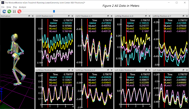
While the data was generally tightly aligned, we were concerned about the large separations that all the technologies exhibited at L5S1 and the hips. In Figure 2, we plotted the X and Y positions of joint centers. The markered subject’s pelvis in the X direction was most out of line with other technologies. Again, the reader is invited to zoom in to read the data. While the X and Y positions varied by less than a couple centimeters for most joints, the X position of L5S1 was different from the other technologies by as much as 9.5 cm. Upon examination, we discovered that the offset to the L5/S1 center from the digitized point for the markered subject had been entered incorrectly during the model definition!
Passive Optical systems that track reflective markers are considered the “gold standard” in motion capture as they have been demonstrated to track reflective markers with less than 1mm RMS error. But it is instructive that accuracy in tracking a marker does not transfer to accuracy in tracking the human body. Soft tissue movement, surface landmarks vs. internal landmarks, and user errors can all impact this “gold standard” as we just demonstrated. How to turn gold to bronze!
Joint Angles
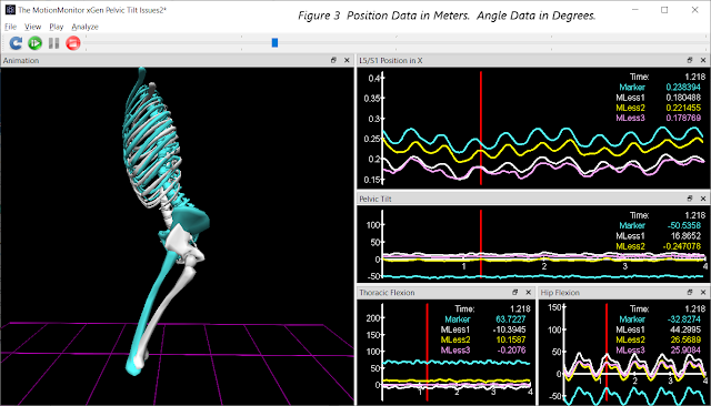
The impact of the error in L5/S1 is significant as shown in Figure 3. Only the pelvic orientations from the two extreme subjects are shown in the animation. What should be a near neutral pelvic tilt is reported as 52 degrees posterior tilt for the markered subject. This will, in turn, understate hip flexion and overstate thoracic flexion. With normal pelvic tilt, the markered subject would generate hip flexion and thoracic flexion angles that are comparable to the markerless subjects.
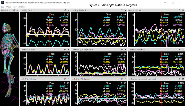
Except for the issue discussed above, the hip, knee and ankle sagittal plane angles in Figure 4 show consistency in pattern and generally fall within 10 degrees of one another. The medial/lateral and transverse plane data do not show as strong a consistency in pattern. Good measurements in these planes of motion have always been more difficult to measure accurately.
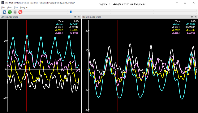
Hip abduction angles in Figure 5 show similar patterns in each stride for all the subjects, peaking and troughing at consistent points (eg. foot contact) in the activity. But most subjects differ in their expression left to right which may be reflective of the subject’s running style.
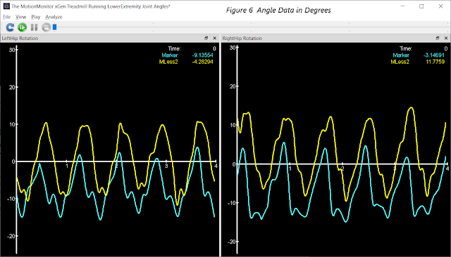
Hip rotation angles in Figure 6 showed consistent patterns in only two of the subjects.
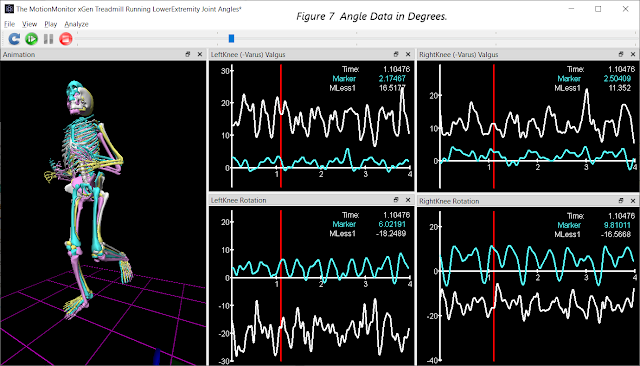
At the knee, medial/lateral and transvers plane data did not show the consistency of sagittal plan data. Only the markered subject and one of the markerless subjects show discernible patterns of varus/valgus and rotation during foot contact in Figure 7 below. In some areas of research, knee and ankle joints will have constraints placed on the measurements to avoid output that is considered unlikely. For example, some systems will prevent the intersection of tibia and femur or constrain movement as a hinge joint instead of permitting movement with 6 degrees of freedom. This could account for the differences in some of the knee rotation data. Understanding model constraints is important for ensuring that user’s objectives can be met with the chosen technology. For example, tightly constraining the knee does not always make sense if the objective is to identify the degree of actual movement as part of a functional assessment.
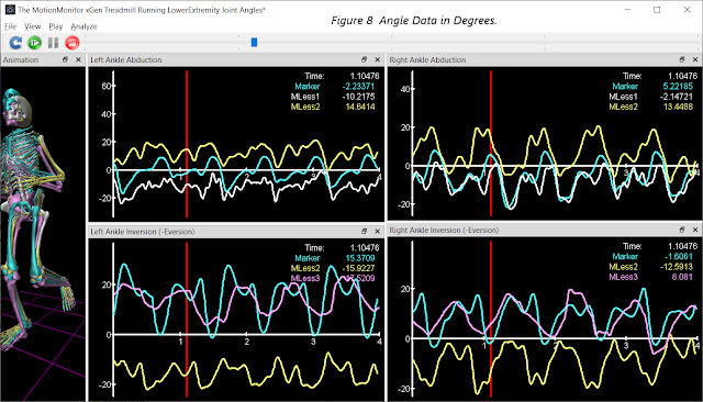
Like the knee, ankle data in medial/lateral and transverse planes (Figure 8) did not show the consistency of pattern or amplitude of the sagittal plane. Only two subjects showed consistencies across strides in medial/lateral plane while a different 2 subjects showed consistency in the transverse plane. Some model constraints are suspected again.
Angular Accelerations
One of our questions concerned the ability of AI technologies to generate data suitable for higher order computations such as joint forces, moments and power. Because these measurers rely heavily on acceleration data, an examination of acceleration data is a good place to start. It is generally understood that acceleration data in biomechanics can be noisy. The graph in the upper right corner of Figure 9 displays the raw acceleration data for the flexion/extension angle of the right knee for each of the markerless subjects. Very noisy indeed! The red is the actual signal for reference. The question is “can this data be filtered in such a way as not to destroy the underlying signal?”
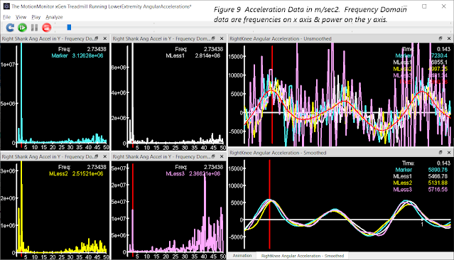
To determine if it is possible requires a look at the noise in each system. The MotionMonitor xGen Frequency Domain functions were used to extract the necessary data. The four plots to the left side of Figure 9 are the same angular acceleration data plotted in the frequency domain (frequency on the x axis and power on the y axis). What each show clearly is that the largest frequency is 2.75 hz for each system. But each system does generate varying degrees of high order frequencies (30-50hz). These high frequency elements likely result from the technology rather than the underlying activity. High order frequencies in the marker data could be from marker vibrations that occur on impact. Noise in markerless data could be associated with how accurately features are extracted frame to frame or the way in which global optimization routines are applied to the results. These high order frequencies can be safely removed without affecting the underlying movement data. The Nyquist or Sampling Theorem would suggest that filtering at 2 times the largest frequency would preserve the underlying content of the signal. The RightKnee Angular Acceleration data filtered at 6 hz appears in the right panel of Figure 9 below the unfiltered data. And all 4 technologies appear very similar in both time and amplitude which suggest that acceleration data should not be an issue in higher order computations.
Joint Force, Moments and Power
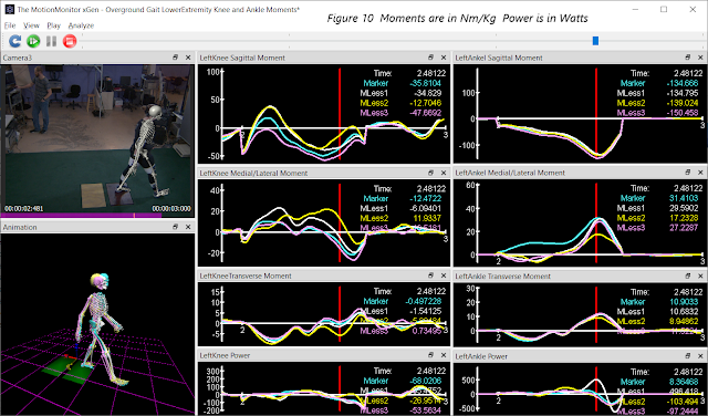
We would expect good results with force, moment and power data given the consistency we have observed in intermediate data. Moments at the right knee and ankle graphed in Figure 10 for overground walking demonstrate a consistency of both pattern and amplitude for all 4 technologies.
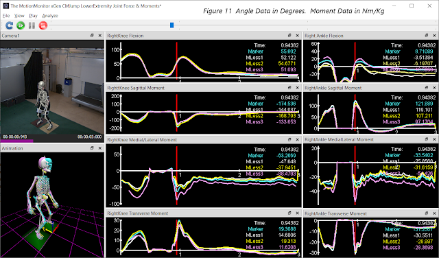
We were also interested in knowing if the type of activity would affect the data. Would these different technologies perform equally well in activities that have faster or more abrupt movement patterns? In Figure 11, a counter movement jump is shown at the point of landing. Here again one sees a consistency of pattern and amplitudes that are within ranges reported in the literature.
Other Considerations
There are other considerations worth mentioning including synchronization and camera calibration. Synchronization of data is always a concern particularly when collecting data from multiple systems. When a markerless system is unable to extract features from a video frame, the missing data can cause a misalignment with the original video file. The data file can start late, end early or have jumps when drop outs occur in the middle of the trial.
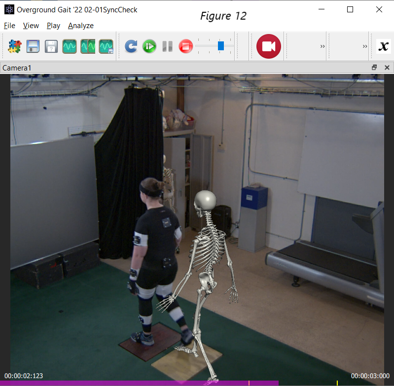
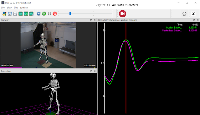
While large synching issues are obvious, smaller ones are not. In Figure 13, a 3-frame misalignment is not obvious in the overlay but can be seen in the time series data. The peak height in these two subjects occurs 3 frames apart demonstrating the misalignment. It is important to understand how each technology handles beginning, ending and mid trial drop-outs as alignment is critical when trying to synch AI generated data with other peripheral data such as EMG, EEG, force plates or eye trackers.
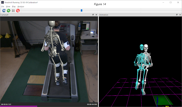
Another consideration involves camera calibrations. Each of the markerless technologies has its own calibration process. With different calibration processes it is possible that technologies may accurately extract the features from the video but then mis-report its location in the world due to a poor calibration. The intrinsic and extrinsic calibration data can have a significant impact on the results as seen in this image with an intentionally poor extrinsic calibration.
Conclusions
As stated earlier, our goal was not to evaluate any of the technologies as being “better” or more accurate than the others. We saw early on that “gold standards” are not what they may seem when the difficulties of applying them (soft tissue artifact, operator error, etc.) are considered. But we did come away believing that all these technologies have a real place in the world of motion tracking each being surprisingly consistent with our markered subject.
1. All appear to consistently extract features which are sufficient to generate biomechanical models that behave appropriately and within expected tolerances for all the data categories.
2. Each technology provided similar consistency across activities with different movement patterns and accelerations.
3. The quality of tracking and generation of data certainly seems acceptable for evaluating performance in sporting activities.
4. The markerless data is comparable to markered data and could be used in pre-post training evaluations.
All the technologies supported in The MotionMonitor have strengths and weaknesses. As a result, different purpose, different types of activities and different environments may suggest the use of different technologies. The benefits of markerless tracking are significant as we discussed in our previous blog. And with the accuracy we experienced in our early usage, it is clear that markerless has a place in motion capture!
If you’d like to learn more about The MotionMonitor with markerless, check out this press release.
Want to see these technologies for yourself? Message us to setup a live demo:
Visit our website, www.tmmxgen.com, for more information about our systems and applications.
Until next time,
Lee


